KMDuino MKII - Home design Arduino clone (UNO R3 Bootloader) with full Arduino Uno
functionality
Greetings from my rather cool shack in Fourways. So last month I said that we would be putting together a few projects over the next few months using Arduino to be used in the shack. Well I was sitting in the shack and thinking about that and decided that even though it is easy to pop over to one of the online stores and just order an Arduino Uno or Mega, I would much rather have one that I built myself. Yes, it is cheaper to make your own, but not by that much and you could possibly pick up one of the grey Chinese products for less, but there is no fun in that.
So here goes building your own Arduino. Enter the KMDuino MkII ( MKII because I have made changes to the original design I did to cater for the 90° TTL programming pins as well as adding a power socket).
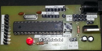
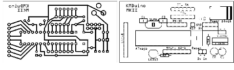
Pictured above is the prototype of the KMDuino, an Arduino R3 compatible device about half the size of the original Arduino UNO, with all the exact same functionality. Below is the PCB and Overlay layout (not to scale). The PDF files to manufacture your own boards are available for download from my website and are listed at the end of the project.
I won’t go into the methodology of making your own boards here, but if you choose to, you can make a board out of Vero board; the circuit diagram for the Arduino Uno is available from the Arduino.cc website and is quite simple to follow. Right so let’s get started.
Components:
1 X Atmega 328P (with bootloader), 1 X 28 pin IC socket, 1 X 16mHz Xtal, 2 X 22pF
ceramic capacitors, 1 X 0.1uF capacitor, 2 X 10uF capacitors, 2 X 220ohm 1/4W resistors,
1 X LM7805 Regulator, 1 X red LED, 1 X DC power socket, 1 X sub mini PTM switch,
some header pins and the KMDuino pc-
Construction:
Construction is straightforward and follows the usual rules for inserting the smaller components first. We insert the two 22pF capacitors and 16mHz Xtal and solder them in place. Next we insert the two 220ohm resistors and sub mini switch. Finally we insert the power socket, LM7805 regulator, two 10uF capacitors and LED taking care to watch the orientation.
I suggested buying an IC socket as it would be simple to remove the Atmega 328P to replace it should it fail. We can now solder that in place tacking pins at opposite end and then soldering all the pins (observe the orientation of pin1). Our last and final step in the construction is to break the header pins into small sections to suite the Arduino functions. If you are using the KMDuino board this is simple as you can just count the holes, or just break the pins according to the following chart.
1 X 9 – D5-
NOTE: Please take the time now to check your soldering for bridged tracks or bad solder joints. We do not want to damage the Atmega chip.
Once you are certain that the board is perfect, you can insert the Atmega chip and
your KMDuino is complete. This design utilises TTL for programming and a suitable
USB-
Download the Arduino software from Arduino.cc and you are ready to start programming your device. There are many tutorials online that will help you get started, but I hope you will try some of the little projects we hope to feature in Radio ZS to add interesting new toys to your shack.
I hope you have fun experimenting with your KMDuino, please share your projects, pictures and stories with us, send them to projects@zs6kmd.za.net and with your permission I will include them in future articles.
Location of files:
KMDuino – http://www.zs6kmd.za.net/KMDuinoMKII.rar
The KMDuino MKII is available as a kit with all components and PCB from my product page.
Happy building
73