Handy Tester from original article by D Mohan Kumar - PCB design by ZS6KMD
I recently decided to build a simple Handy Tester, a small piece of equipment that everyone should have in the shack for testing the condition of components, from resistors to IC’s. The original article was provided by D Mohan Kumar and the PCB designed by ZS6KMD.
The circuit diagram below is simple to read and the explanation that follows explains how it works.
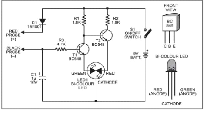
The circuit is extremely simple and exploits the biasing property of bipolar transistors. Transistors T1 (Q1) and T2 (Q2) act as transistor switches driving the red and green halves of bicolour LED1 independently to give results of the test.
When power is applied to the circuit by pressing switch S1; transistor T1(Q1) stops conducting due to the lack of forward bias. At the same time, transistor T2 (Q2) gets a base bias voltage from the battery through resistor R1 and conducts. This allows the red half of the Bicolour LED to become illuminated.
When the base of transistor T1 (Q1) gets positive voltage through resistor R3, it conducts to light up the green half of bicolour LED1. When transistor T1 (Q1) conducts, the base of transistor T2 (Q2) is grounded and it cuts off to turn off the red half of bicolour LED1. The functioning of the circuit thus depends on the signal obtained at the base of transistor T1 (Q1).
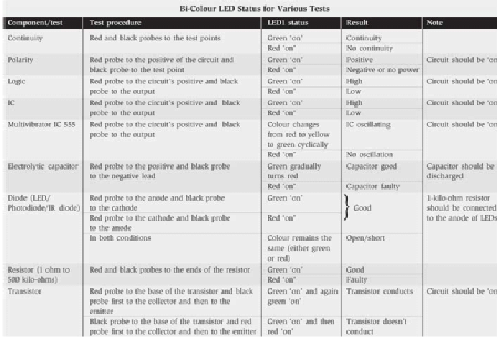
The table gives the testing procedures for various components with the expected indications/results.
Construction:
The component count for this project is very low and construction is straightforward. The project can be built on a small piece of Vero Board or a PCB can be purchased or made using the artwork provided on the link at the end of the article.
Components:
2 X BC548, 1 X 1.5KΩ, 1 X 1.8KΩ, 1 X 4.7KΩ, 1 X 1uF 16V Electrolytic Capacitor, 1 X 1N4001 Diode, PCB, Probes, Switch and 9V battery.
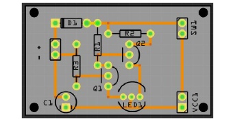
PCB Layout:
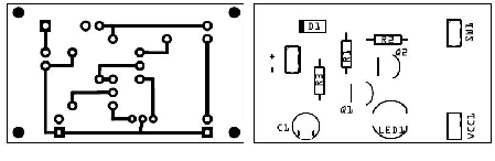
The PCB files are available on the ZS6KMD website on the following link. A complete kit is also available containing all components and a PC board.
Links:
http://www.zs6kmd.za.net/handy_tester.rar
Please send me pictures of your Handy Tester so I can show them in future articles, mails can be sent to projects@zs6kmd.za.net – If you have a project idea or contribution please submit it to the same email address.
73