Revised ZS6KMD ALC Controller
With so many QRP operators fuelling the ether, so many new QRP contests and field stations joining the ever growing challenge of miles per watt, I thought I would write a short piece on making a non intrusive modification to your QRO transceiver to allow you to join the throngs and really work true QRP. The origins of this article lay with OM Bob N4BP. The original design was built into a small box and ugly wiring used to make connections to a two cell battery holder. Not being a huge Guru on PCB design, please forgive my crude layout. I have made a simple PCB design to make the device look neater, smaller and more durable.
ALC QRP Adjustment Controller
Most HF transceivers have access to an ALC control socket at the rear of the device. This was originally intended for use while using HF Linear amplifiers. OM Bob N4BP provided us with his design to an old solution where using a battery and potentiometer would apply a negative voltage to the ALC control line, reducing the RF output to a lower level. The original circuit had too much sensitivity and was modified using 3 potentiometers allowing a low/high threshold to be set. This reduced the sensitivity to a manageable level.
How It Works
When the negative voltage is applied to the ALC Circuitry, using R2 and R3, set the minimum and maximum RF output (I have set mine for 2 and 10W). Using R1, the output can be varied accordingly. Make use of an accurate RF Power Meter to verify your output. Because this is non intrusive, no warranties will be voided. However make sure that your connections are correct and do not cause short circuits.
Fig 1. Schematic Diagram of ALC Adjustment Controller
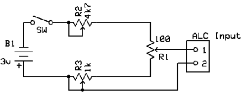
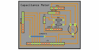
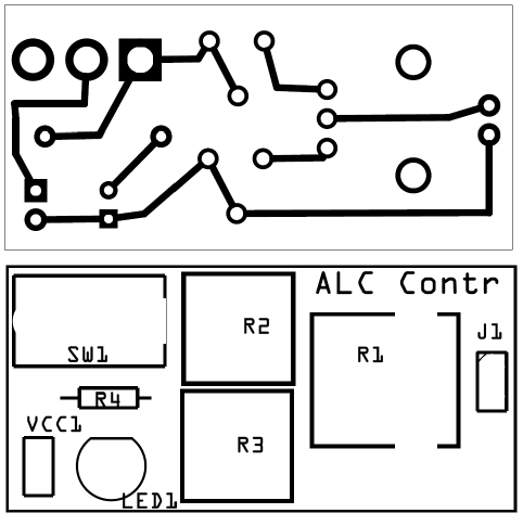
Fig 2. PCB Layout of ALC Adjustment Controller
Parts List
R1 – 100 Ohm Pot R2 – 4.7K Ohm preset Pot R3 – 1K Ohm preset Pot Plug to suit ALC socket
B1 3V Button cell B1/H 3V Button cell holder Suitable case or holder SPST Toggle switch
Remember when not using the device to switch it off as the circuitry does draw a small amount of current (80µA). An additional mini LED indicator could be added to show power on or off. Spare button batteries could be carried inside the enclosure ensuring that you always have power for your ALC controller.
Artwork is available from the website as usual.
Web link: http://www.zs6kmd.za.net/ALCv2.rar